|
Foreward
It seemed like a good idea, making a folded di-pole antenna. Seems interesting to me that it inherently is 2.15dB gain over isotropic, at a minimum. I have a good isotropic antenna but I want to explore broadcasting distance at the 50W power limit with folded dipole and imaybe I could be able to receive more signals on other bands, maybe my antenna could be better. At the same time, if I could use a lower power signal for the same reach locally, all the better as well. I targeted the 70cm band and GMRS for the range; 441 MHz (with -5 offset) to 467 MHz (with +5 offset) and a median of 453.5. Another caveat of the expirement is to avoid need for impedance matching to use the new antenna.
I will remind you, this is not a scientific approach. I am assuming that all those experienced radio dudes already have determined the electrical and emission characteristics involved with a folded dipole. I am just working on the mechanical part of creating one.
At first, I thought it would be best if I just made the elements the full wave, better to catch all of the signal right? Then somewhere, maybe a little later than I would like to admit, I found out the impedance would not work out unless I used half wave. It seems that with each cycle the whole antenna will change polarity twice, called a resonant event, and emit a wave best created from a half wavelength element electrically. Resistance at resonance of the folded dipole is 4:1 over a regular dipole. This is about 280 Ohms for each element.
Math
First, I wanted to do all the math and prove the concept on paper. I have to get some material, so sizing the elements will determine the materials I need. We know that "speed of light" = wavelength * frequency. Re-arranged, wavelength = Frequency / speed. We also want to have half wavelength. Finally, the conduction rate for speed of light in the element will be reduced at a factor of about 0.951, so we need to factor that in. So, here is our equation.
(3*10^8 / 453.5*10^6)*39 = 24.535 |
(25.297 / 2) * 0.95 = 12.7675 |
| where |
| | 3*10^8 | Speed of light |
| | 453.5*10^6 | Target frequency |
| | 39 | Inches per meter |
| | 0.951 | Speed of electricity in wire |
So the total length of material needed for each element will be at least 24.537 plus the bends, and folded length will be 12.7675 inches on the inside. Since the highest frequency is the smallest wavelegnth, we are going for ID.
I just happened to find several hundred feet of 3/4 inch stainless tubing left behind from a contractor job. There was even a bender, how nice! Had I have recalled just how difficult it is to bend 1/2 inch tubing, I may not have started down the road of using the 3/4 inch - but there are benefits we will talk about later. Two 20 foot sticks is all I need for this little job, and that should give me enough for my mistakes. As part of the learning curve, a later rebuild is planned with 5/32 stainless rods. The wider bandwidth has lower sensitivity.
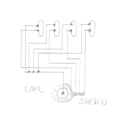
Network
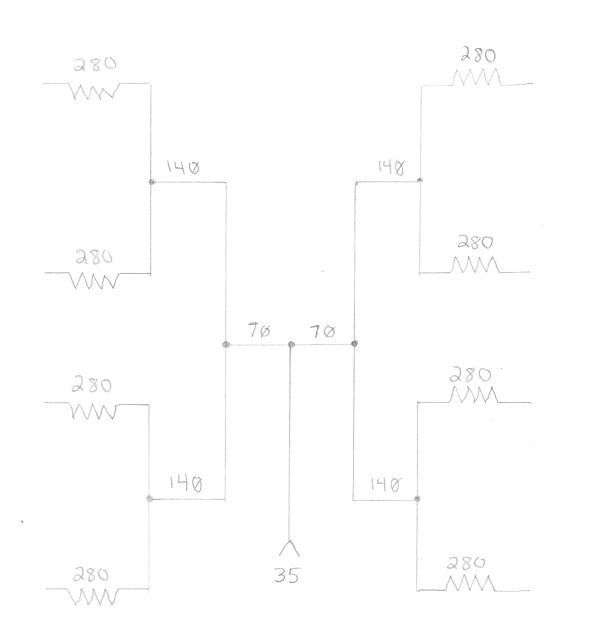
Another goal of this expirement is to match impedance with the LMR400 and my base radio. I do not want to have to add more equipment to use it, ie balun. That means a network of elements, or an antenna array will be needed.
If resonant resistance is 280 Ohms on each folded dipole element, we will have to do some math and determine how close we can match the impedance by arranging the elements is series or parallel circuits. Ideally we have to get down between 30 to 70 Ohms. I like the higher side to keep from burning up the radio I am going to hook up to. That will help prevent over-driving the amp in the radio.
Mathematically, it seems like an 8 element array will get me down to 35 Ohms. That is too much, not enough load for me. 4 elements leave me at the target 70 Ohm area. Another key to the impedance matching is all elements resonating at the same frequency and at the same time. All wires to and from each element will have to be the same length for this experiment.
I have some reservations about the exact impedance matching with the home made elements and have a plan to test the system with an amp meter and the SWR meter at low power first. When we find the radio is not over-driving the antenna we will move on to signal testing at higher power.
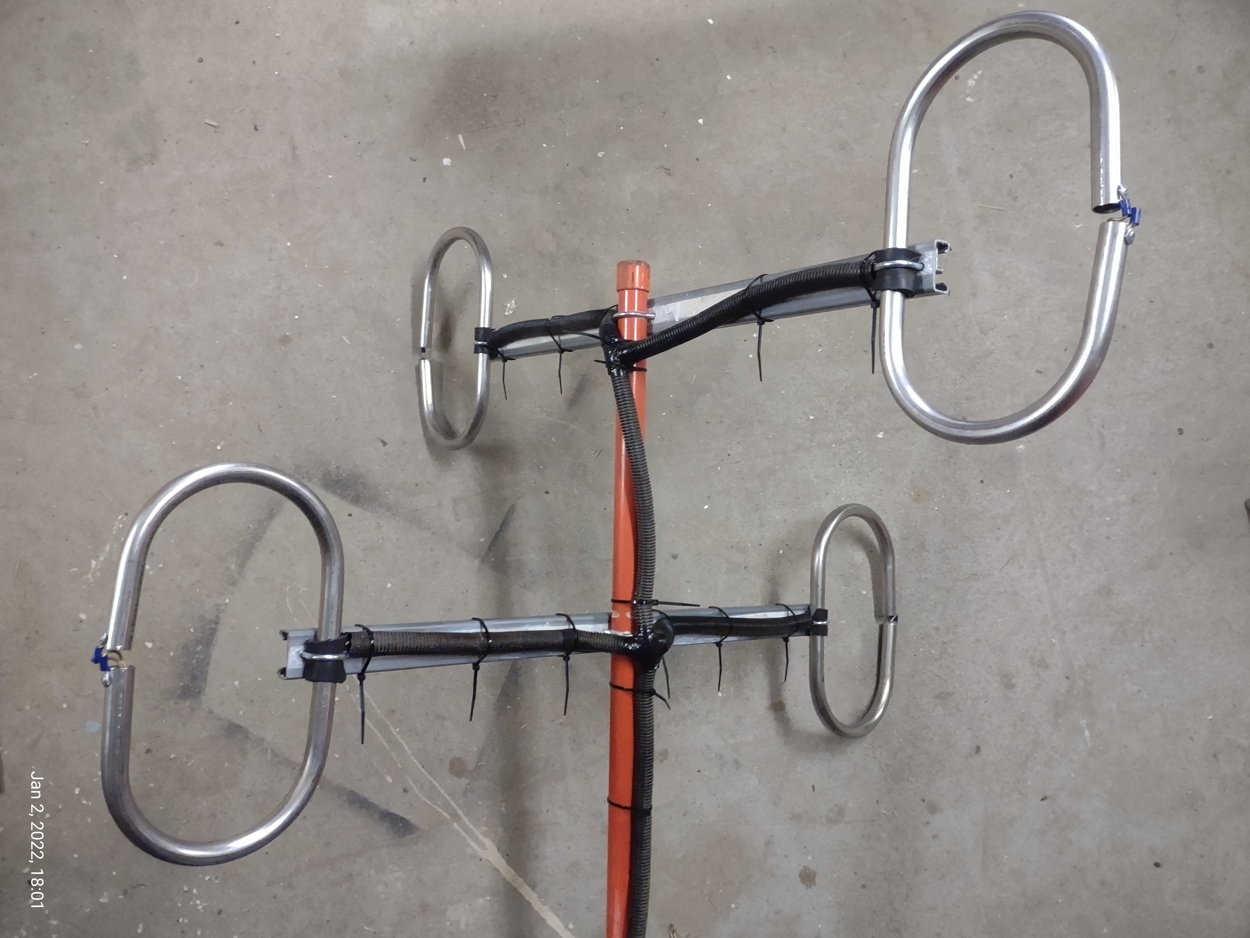
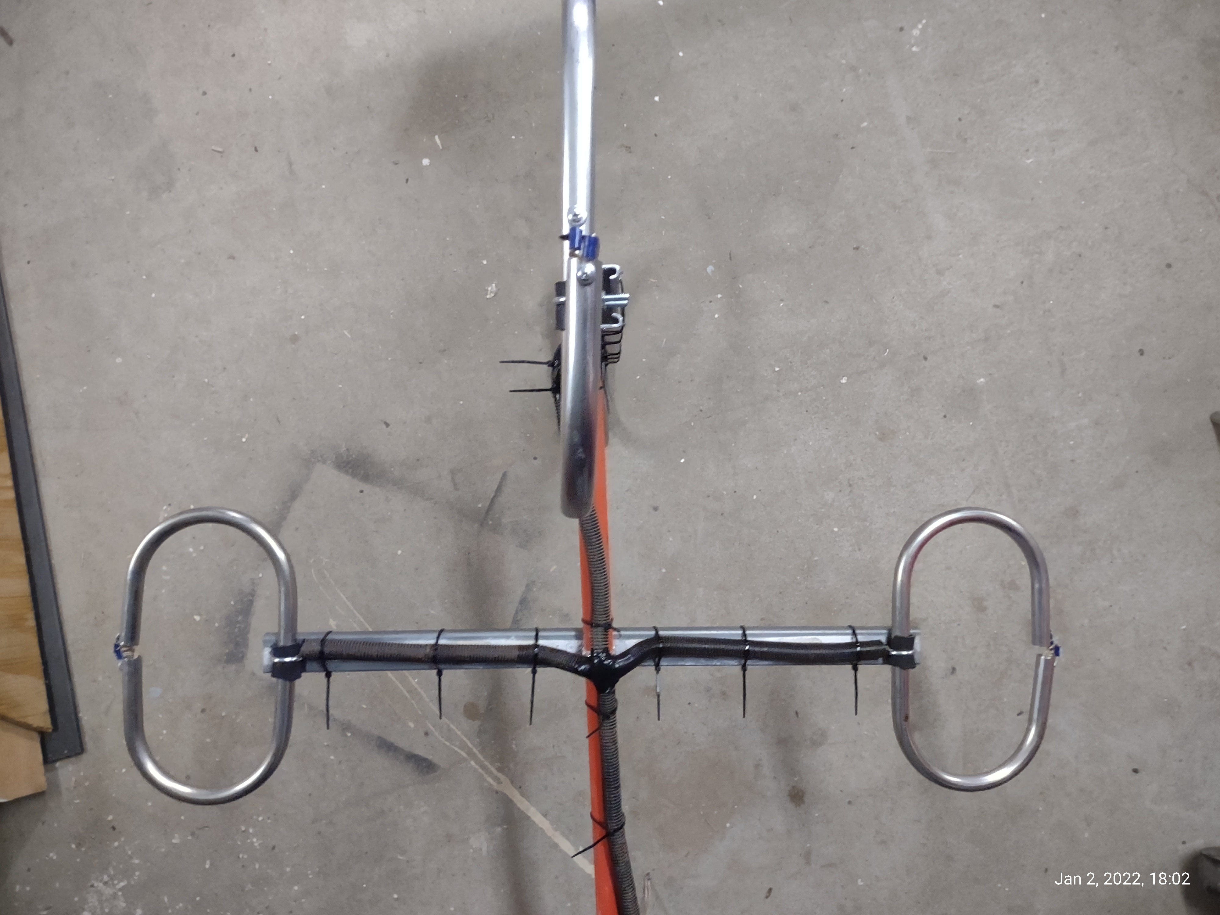
Mechanics
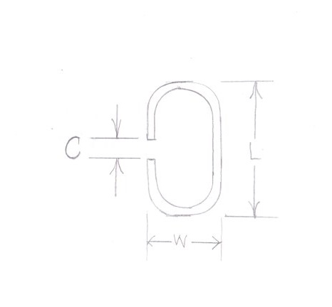
The element itself also has some key components that can change the resonating frequency and impedance. On the left, the critical measurements are labeled.
L is critical to be 12.7675 inches plus 2D (14.26) for our target frequency. I picked that out of uncertainty of the experiment results. GMRS is the target band this time. I have not mentioned it yet, and it is not in the diagram, but the element diameter will also help with bandwidth. I have been targeting the middle of the GMRS bands for the wavelength, but with 3/4 inch tubing I should have something just over 25 Mhz bandwidth between ID and OD of these elements. Just for an idea, 462.7 Mhz is about 12.011 inches at half wave and 0.951 factor, 442.5 Mhz is 12.016 inches - only .005 inch difference. I have seen it speculated also that the diameter could effect the the light speed factor. For all of GMRS and 70cm, with offset there is about 1.6 inches in 1/2 wave for the spectrum.
W is not critical but can effect the impedance. I am going to use 3 inches because of the bender I have. Can't really adjust that one.
C is not critical but will also effect bandwidth. I am targeting a 1 inch gap but could be difficult with the large diameter tubing.
If the outside diameter of the oval will be 14.26 inches, and the outide bends are going to be 3 inches, I calculate the total length for each element should be 25.2 inches. 8.5 inches in each curve, 4.2 inches on the long side, and 2.5075 inches on each short side with a 1 inch opening.
So, we will cut to 25.2 inches and bend the 3 inch curves at the 2.51 inch mark of each end. I doubt I can get closer than that in measurements. I will also drill a hole in the bottom of these elements for a drain.
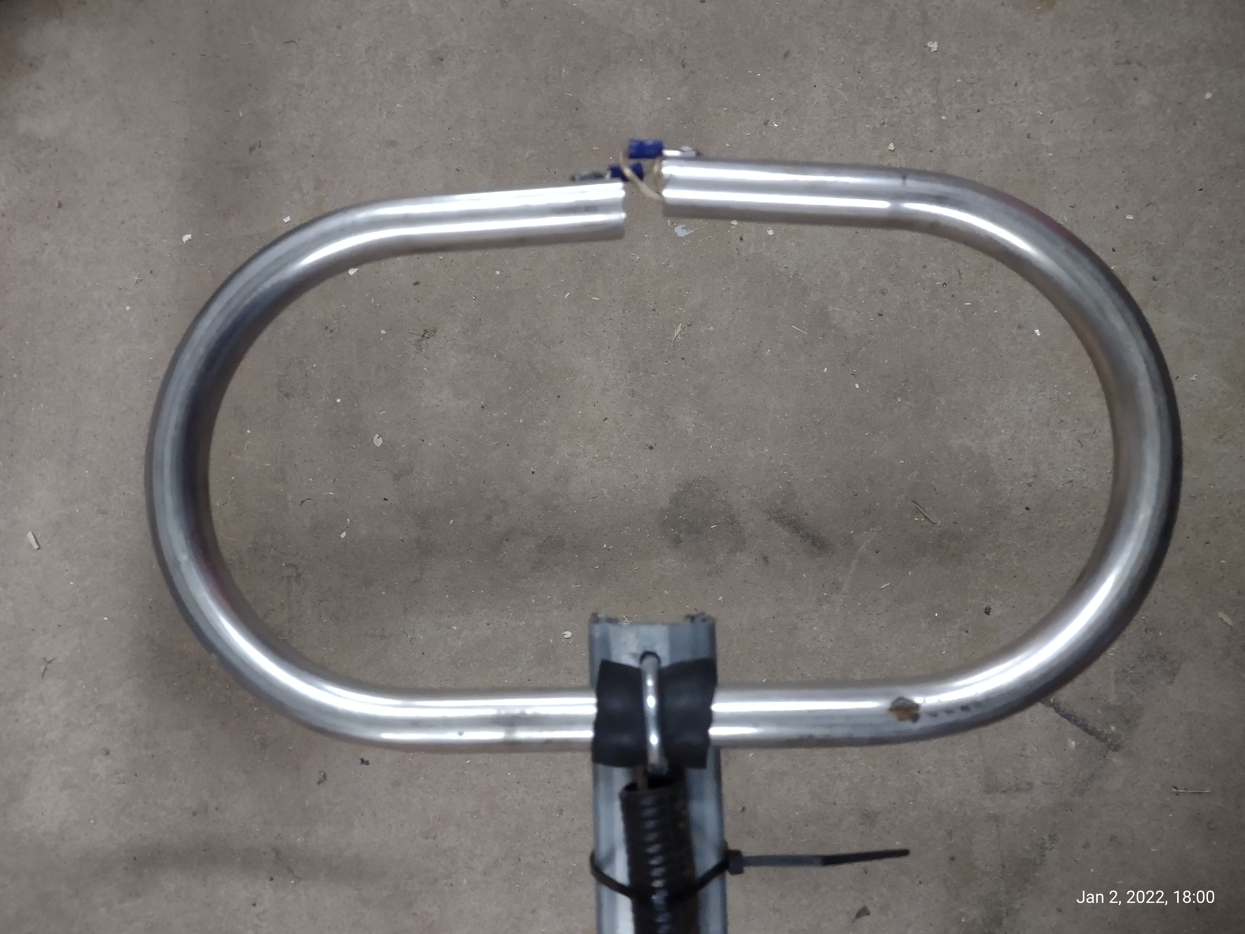
I was fortunate enough to get the gap down to about 3/8 inch. It was tricky but I felt it was a little important and worth the effort.
For the wire, 10 gauge should be a great conductor with minimal loss when the joints are soldered together. Remember, the wires all have to be the same length. If you also use stainless elements, you will also need silver solder for a stainless soldered connection.
Testing
I wanted to test the elements before soldering. After bending, and finding out how difficult that was going to be, I cut the wires to length for the final pole design and just wire-nutted them together temporarily spread out on the floor for a test.
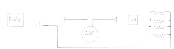
With the radio in low power, I tested on some of the bands on the local plan outside of the repeaters. I had a constant 13.7 VDC power supply to the radio, and measured 0.35 amps on the circuit. I tried a couple bands in GMRS, then moved up and down to find where the amperage started to climb. These would be the bandwidth limits. I found the SWR and power consumption was good in the 70cm band and the GMRS! Nice. Just for another check, I went in to the repeater bands and was able to hear traffic with the elements lying on the floor. Double nice. Some final testing was done in high power in 70cm and GMRS. Still good on the power and SWR. Remember, Power = voltage * current.
Lastly, I acquired a few feet of stainless unistrut to support the elements on the pole. I will insulate those with a rubber insert inside a u-bolt pipe clamp. Spacing the elements 1 wavelength apart center to center will prevent interference betweed the elements for a perpendicular omnidirectional array arrangement. I am going to weld together a couple sticks of 2 inch schedule 40 pipe for the pole. The pole will be supported by the house.
Summary
In the end, I was able to create an network array that electrically demonstrated the characteristics expected with the specifications that I had estimated. Most everything was found on numerous other websites and compiled into the project. I do also have some questions about the amount of power lost to a higher take off angle.
This is my primary antenna now. I typically only talk on the 70cm and GMRS bands anyway. Most importantly, I can reach the GMRS repeaters 90 miles away now with 5 watts where I had to use 15 watts before. I was also hoping for the ability to pick up more traffic on other bands, but one of the lessons learned is that the bandwidth of the antenna is inverse to the sensitivity. Next one will be made from 5/32 inch stainless bar with a target ID for 467 Mhz. Even with the reduced sensitivity, the other day I heard a broadcast from a canyon area just over 180 miles away in the 446 MHZ frequency range. An antenna switch could be added to this antenna with my 4 band isotropic antenna if I wanted to go back to more bands and sensitivity from the base station.
All in all, this seems to be a good recipe for a folded di-pole. Good luck with yours.
|